
Introduction
As concerns about climate change increase while global demand for energy continues to grow, we are committed to ensure a sustainable future by reducing and ultimately eliminating anthropogenic (caused by humans) Carbon Dioxide emissions in the atmosphere.
Carbon Capture, Utilization and Storage (CCUS) is one of the methods to reduce carbon dioxide emissions required to reach the goals of the Paris Climate Agreement.
Captured CO2 from a variety of sources (power plants, refineries, chemical plants), can either be used for industrial products, for greenhouses or can be transported for long-term storage in geological formations e.g. depleted gas reservoirs or saline formations.
However, large CO2 emitters (Power Stations or Industry) are typically located nearby populated (sub-) urban areas. The routing of CO2 pipelines and storage of CO2 near densely populated areas proved to be problematic. For example, in the last 10 years in the Netherlands, onshore CC(U)S projects in Barendrecht and various locations in Groningen and Noord Holland have been cancelled after protests from citizens and municipalities, who consider CO2 storage in their area an unacceptable risk. Main risk is reservoir seepage and leakage through legacy wells, but CO2 leakage from the transport pipeline is a risk. Also, increasing pressure in the reservoir may induce seismicity, a sensitive topic in The Netherlands.
An offshore storage location enhances acceptance of these risks. In Europe the Snøhvit pipeline in Norway is one of the few offshore CO2 pipelines to date, but currently various CO2 studies and projects in Norway (Northern Lights), the UK and NL are underway based on offshore storage with associated offshore pipelines.
The PORTHOS consortium (Port of Rotterdam CO2 Transport Hub & Offshore Storage) have initiated a plan to collect CO2 from the industrial area of the port of Rotterdam and transport it to an abandoned gas field offshore for storage.
Offshore Independents B.V. has performed an initial feasibility study and developed the Concept Selection/Pre-FEED study for the offshore pipeline part of this project. Some aspects of this study and some general observations are outlined below.
The project involves CO2 capture, transport and storage in the depleted P18-A gas field approximately 25 km from the onshore compressor station located on the Maasvlakte. A 30 km 42-inch onshore gathering pipeline transports the gaseous CO2 at 35 barg to the compressor station where the CO2 is compressed to 130 barg and dehydrated for transport to a former gas production platform via a 25 km 16-inch subsea pipeline. The CO2 is then injected via existing wells into a sealed reservoir of porous sandstone 3 km beneath the North Sea.
A similar project is being developed by ATHOS (Amsterdam-IJmuiden CO2 Transport Hub & Offshore Storage)
CO2 Pipeline Design
Design and construction of CO2 pipelines are similar to natural gas transmission pipelines. However, there are important differences as listed below:
- Thermodynamic modelling (especially when dealing with impurities present in CO2),
- Blow down modelling (low temperature control), specifying the maximum water content (corrosion control and fatigue behaviour),
- Pipeline fracture propagation control (brittle fracture),
- Use of elastomer materials and
- Performing a QRA (Quantitative Risk Assessment, mainly related to release modelling and defining the allowable exposure limits).
These factors require special attention for CO2 pipelines, when compared with natural gas.
Flow Assurance
Pipeline transportation of CO2 over longer distances is most efficient and economical when the CO2 is in the dense, i.e. in liquid or supercritical phase. This is due to the lower friction drop along the pipeline per unit mass of CO2 compared to transporting the CO2 as a gas or as a two-phase combination of both liquid and gas. Vapour phase CO2 is normally not used in long distance pipelines in large quantities, however it is being transported over short distances to greenhouses in the Netherlands.
Although the thermo-physical properties of CO2 are different from those of natural gas, the handling of CO2 is quite feasible during normal operation. However, due to phase changes, the effect of Joule-Thomson cooling and the risk of hydrate formation, transient conditions like start-up, controlled and emergency shut-down and pipeline re-pressurisation will require special operational procedures.
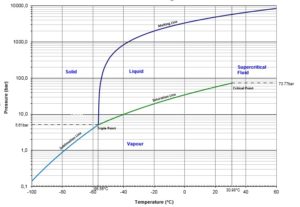
At normal atmospheric pressure and temperature, the CO2 phase is vapour. Above the saturation line it is in dense phase, either liquid or supercritical. A supercritical fluid has the viscosity of a gas but the density of a fluid. Reducing the temperature and pressure results in a phase transition from liquid to gas with a change in enthalpy and density. This change requires heat to be added causing reduction of temperature, possibly resulting in formation of solid CO2 known as dry ice (see below phase graph from DNVFG-RP-F104).
Normal Operation
When operating the Porthos pipeline, a balanced approach is required.
At the start of CO2 injection into the wells, the down-hole pressure will be quite low (20 bar). A large pressure difference between the pipeline and the wellhead will cause a significant temperature drop due to the Joule-Thomson effect. The down-hole temperature should be kept above 15°C in order to eliminate the risk of hydrates formation.
Because the pressure drop is restricted by the temperature limitations, the difference between the dense phase pressure and initial reservoir pressure is considered to be too high.
Therefore, the pipeline must initially be operating in vapour or two phase condition with no pressure drop at the well choke until the reservoir reaches pressures allowing dense phase supply. This condition limits the injection rates.
The impact of the cooling and the risk of hydrate formation can be mitigated if the temperature of the CO2 in the pipeline is sufficiently high. This can be achieved by preserving the temperature generated at the compression/dehydration train by applying thermal insulation on the pipeline.
At the dense phase supply stage, the downhole pressure is achieved by hydrostatic pressure of the injected CO2 rather than the pipeline pressure. In order to reach the final downhole pressure, the density should be high enough and therefore the temperature should be limited by applying cooling downstream the compressors. (see below mass density graph). Injection pressure and temperature needs to be controlled to ensure injected CO2 at the bottom of the well is in supercritical phase.

Commissioning
For carbon steel pipelines, internal corrosion is a risk to pipeline integrity. The primary concern is the presence of free water in the pipeline that, combined with high CO2 partial pressure, will form carbonic acid. Special attention should be given to dewatering and drying of the pipeline system prior to filling. The high solubility of water in dense phase CO2 may be sufficient to avoid free water compared to gaseous state. However, in the initial stage of the first-fill, the CO2 will be in gaseous phase wherein the solubility of water reduces with increased pressure and free water may form. The solubility can also be significantly affected by the presence of impurities.
The pipeline should be dried to a dew point of -40°C to -45°C (at ambient pressure) before filling with CO2.
During initial filling, when CO2 is throttled downstream the compressor, low temperatures and formation of solid CO2 that may block the pipeline shall be considered until high pressure is reached.
Depressurization
Depressurization of a CO2 dense fluid pipeline (required for maintenance, in emergencies or at decommissioning) shall be done in a controlled way based on temperature measurements and may take a long time (days – weeks). This is to avoid temperatures lower than the design temperature and the formation of solid CO2 at low points in the pipeline which may plug the pipeline and will take much time to sublimate to vapour.
It is recommended that the temperature during the process is kept above -20°C and that pipeline materials are specified for an even lower temperature.
The depressurization follows these phases:
Initially, the pressure drops quickly when the fluid is in the dense or liquid phase, as a small reduction in inventory results in a relatively large reduction in pressure due to the relatively low compressibility.
Due to pressure reduction, boiling of liquid CO2 will cause heat to be absorbed from the pipe wall and surrounding soil thereby reducing the metal temperature to close to the fluid temperature. In addition, J-T cooling will occur as the CO2-rich gas expands and the pipeline inventory is reduced through venting.
When the fluid temperature approaches -20°C, the depressurization is stopped to allow heat recovery from the surroundings. During this time the pressure increases slightly as the gas heats up and expands.
The temperature recovers and the pressure can continue to drop. The CO2 will enter the gas-only region and heat supplied from the surroundings has a greater impact on the fluid temperature due to the lower heat capacity of gas compared with liquid or two- phase CO2.
Pressure Surge Summary
The maximum pipeline pressure is below the maximum incidental pressure in the onshore and offshore pipelines, therefore pressure surge following sudden ESD valve closure (hammer) does not cause a pipeline integrity issue. The lack of appreciable pressure surge is due to the compressibility of the dense phase CO2, which is significantly higher than say liquid water.
Water Content
Depending on the operating philosophy of the pipeline, the water content should be strictly controlled. The strictest control is for pipelines
without free water along the pipe wall. Such pipeline has a water content of typically lower than 100 ppm. The CO2 pipelines allowing a higher water content (250 ppm and above) do have to make special arrangements in terms of corrosion allowance or control. The maximum water content of the pipeline should be evaluated on a case-by-case basis. The requirements and cost of the dehydration unit and impact on other parts of the system (pipeline, well and reservoir) must be evaluated as it may prove to be very valuable to have a TEG unit installed. Several experiences are known where the absence of a dewatering unit proved to have detrimental results, while control on the water content was lower than expected.
Impurities
The composition of the CO2 stream will depend on the source and technology for capturing the CO2. The physical properties of a CO2 stream may be affected by its chemical components.
Different combination of impurities may cause cross chemical reaction followed by drop out of an aqueous corrosive phase.
The combination of impurities also has effects on the saturation pressure of the pipeline, which is important for the pipeline design for running ductile fractures.
Presence of impurities may alter the water solubility of CO2 and may increase toxicity in case of accidental release of the gas. the impact of small amounts of contaminants, as often present in CO2, is less well-defined. The impact of specific contaminants on water solubility, corrosion rate and fluid properties, as function of temperature and pressure, should be confirmed at an early phase of a CO2 pipeline project.
Materials
The pipeline material has been selected based on the required resistance against internal corrosion and fluid temperature. High CO2 partial pressure combined with free water will cause severe internal corrosion due to formation of carbonic acid. When the water is in solution in the CO2, there is no problem. The water content of the Porthos CO2 stream is controlled such that no free water will occur in the pipeline.
Corrosion resistance alloys, clad steel or PE\liners are therefore not required; Carbon–Manganese steel is considered suitable for this pipeline.
While not subject of this white paper, it is worthwhile to note that CO2 injection wells are mostly designed in CRA (corrosion resistant alloy) materials. This is because significant corrosion risk is present. While adopted for wells, applying CRA is not a cost effective for pipelines and would make it very expensive. Rather than using CRA materials, the pipe material remains carbon steel, but with special considerations as further outlined here below.
The requirements for pipeline materials and welds shall suit the very low temperatures as a result of depressurization of the pipeline.
Ductile fractures may develop from small cracks due to corrosion or impact. If the pressure in the pipeline exceeds the pipe wall resistance against fractures, the crack may propagate along the pipeline. To arrest ductile running fractures, the decompression rate of the fluid needs to be sufficiently high. The decompression rate of liquid CO2 may be high, but as vapour starts to form, the decompression rate drops significantly. To that extent running ductile fractures is a higher concern for CO2 pipeline than for natural gas pipelines.
The pipeline shall have adequate resistance to propagating fracture. This can be achieved by specifying a minimum ductile/brittle transition temperature confirmed by a Drop Weight Tear Test (DWTT) and minimum toughness test (Charpy V-notch impact test)) at the minimum design temperature. The fracture control can be augmented by an increased wall thickness, or installation of fracture arrestors at appropriate intervals.
The higher toughness of line pipe also imposes more stringent requirements on welding of CO2 pipelines. With suitable welding procedures and making use of experienced pipeline contractors it should not be more complex compared with typical gas transmission pipelines.
The Porthos pipeline is protected against external corrosion by 2.5 mm 3LPP (3-layer polypropylene) anti-corrosion coating. Thermal insulation is provided by 35 mm PUR within a 7 mm casing from HDPE (high density polyethylene). Seabed stability is ensured by the application of concrete weight coating.
The severe radial and longitudinal forces applied by the tensioners during pipelay require certain shear resistance between the different layers: pipe wall, anti-corrosion coating, thermal insulation, casing and concrete weight coating. Shear resistance shall be specified and sufficiently tested during fabrication.
Cathodic protection is achieved by the application of sacrificial half shell bracelet anodes attached to the pipeline. The anodes material is aluminium alloy.
The elastomer sealing materials typically used in valves (O-rings, seals and seats) and other pipeline appurtenances (e.g. pig trap doors, pigs) should be qualified for CO2 service. Especially in dense phase the solubility of CO2 into elastomers can be significant. This could result in swelling and blistering during depressurization. Therefore, selection of suitable soft materials is critical.
Quantitative Risk Assessment (QRA)
Risk assessment considers the likelihood of failure and the consequences of failure. The consequences of failure are linked to the pipeline content and the human activity around the pipeline.
Accidental release of CO2 from an initial liquid state to ambient conditions involves decompression and expansion of the released medium with a corresponding drop in temperature of the medium and remaining inventory. Release may appear as a combination of gaseous and solid state CO2.
A release cloud onshore or on a platform, where humans may be present, may lead to inhalation of the gas. The density of gaseous CO2 is 50% higher than that of air and dispersion may not be immediate. Exposure to air with concentrations of more than 2000 ppm CO2 is considered hazardous. The acute health effect of concentrations of inhaled CO2 above this level ranges from headaches, dizziness and difficult breathing, to unconsciousness and even death. Other risks are inhalation of solid CO2 particles, cryogenic burns and the noise level of the escaping gas.
In the case the subsea pipeline carrying CO2 suffers a leak or rupture, the CO2 will form a jet stream injected into the surrounding water resulting in a bubble plume. The plume will disperse into the atmosphere under influence of weather conditions.
Release modelling and defining the exposure limits for CO2 pipelines are still an area of further development. The effects of a release and how to mitigate and / or respond are not yet fully known, hence an enhanced safety class and inspection regime is recommendable. Current release models have only been validated against a limited data set, and models show significant variation in results. As the findings of a CO2 pipeline QRA are governed by these topics, it is advised to perform a QRA at an early phase of a project and incorporate results from the latest research available, especially for pipelines in populated areas.
In assessing the probability of pipeline or riser damage resulting in a leak, the following external hazards shall be considered:
- The pipeline being hit by a dropped anchor, or being hooked by a dragging anchor,
- The pipeline being subject to loads imposed by a sinking vessel,
- The pipeline being hit by fishing gear,
- The pipeline being hit by a dropped object.
- 3rd party activities such as work barges, supply vessels and rigs.
The probability of likely damage by the mentioned causes is classified as low.
The CO2 pipelines will have a minimum soil cover of 1.0 m over its top. Therefore, the possibility of damage due to fishing gear contact is considered negligible.
Work vessels have designated anchor locations. Work over rigs has designated foot print area.
As a protection measure, the pipeline near the platform will be covered by stone dump to prevent external damage by dropped objects. The riser will be protected against collision by a riser guard and the future tie-in connection on the seabed will be covered with a protection frame.
The probability of damage to the offshore section of the pipeline resulting in a leak is less than
10-6/km/year which is in accordance with the applicable pipeline code.
Conclusion
For the mechanical design of CCS pipelines, key subjects of attention are water content, material selection/specification, fracture toughness control and QRA (incl. pipeline routing, dispersion modelling, exposure limits). These subjects require more specific attention ensuring a safe and cost effective pipeline design. CO2 pipelines can be designed and constructed in a similar manner as gas pipelines. When a slightly more conservative design is adopted, there are no barriers present for development of future CO2 pipelines.
References:
- DNVGL-RP-F104 Design and operation of carbon dioxide pipelines
- TNO 2019 R10335 – Porthos – CO2 injection
- Offshore Independents – Port of Rotterdam Concept Selection Offshore CO2 Pipeline
- 2016-04 IEA Environmental Projects Ltd – Operational flexibility of CO2 transport and storage
- porthosco2.nl