Aleksei Guliaev – Offshore Independents BV
Introduction
Carbon capture and CO₂ transport by pipelines are becoming increasingly popular in accordance with Global CCS Institute`s, Global Status of CCS 2024 report. Numerous conferences, LinkedIn posts, studies, joint industry projects (JIP), and large-scale initiatives highlight the growing interest in this field. While there is a wealth of technical knowledge available online, much of it is targeted at professionals with solid process engineering backgrounds, making it less accessible to engineers with limited exposure to process design.
One of the primary reasons CO₂ transport differs from natural gas (NG) transport is its complex phase behavior, requiring a deeper understanding of thermodynamics and fluid dynamics. This paper aims to: Explain the key differences between CO₂ and NG pipeline transport by highlighting unique properties of CO₂ and their impact on pipeline design and operation and present these differences in simple and accessible terms, making the topic more approachable for engineers who do not specialize in process engineering.
Certain CO2 properties cause the difference with NG transport:
• CO2 Phase behavior
• CO2 behavior change due to impurities
• CO2 molecule structure
These properties and their effect are explained by answering the following questions:
1. Why is CO2 sometimes Transported in Dense Phase while NG is always in Gas Phase?
1.1. Transportation of dense phase is less energy consuming?
2. What is the phase diagram of CO2 and why is it important?
3. Why is it important to know impurities?
3.1. Why does CO2 contain impurities different than natural gas?
4. Are both NG and CO2 pipelines operated differently?
4.1. Why does CO2 cool faster than natural gas?
4.2. Why does CO2 deteriorate seals faster than natural gas?
4.3. Why are CO2 pipelines more prone to Running Ductile Fracture than NG pipelines?
1. Why is CO2 Sometimes Transported in Dense Phase while NG is always in Gas Phase?
CO2 can be transported in a gas phase, similar to natural gas. However, when CO2 is transported in a dense phase, more amount of CO2 is delivered per hour. That is because the density of liquid is higher than a gas.
Why NG is never transported in liquid phase? To liquify natural gas (which is mostly methane, CH4), one need to freeze NG below -60°C at 60 bar. It is technically doable (LNG for example) but not practically feasible in pipeline transport because:
a) Metals become brittle at such a low temperature
b) Liquified natural gas quickly warms up
But how CO2 is transported in liquid phase? How the low temperature problems are solved?
CO2 becomes a liquid at much higher temperature, it can be kept liquid at 20 ˚C if pressurized to 100 barg. Hence cryogenic problem inherent to liquified natural gas is not necessarily applicable to CO2. So, CO2 can be transported in liquid phase, but why we do transport in liquid phase? There are two items to consider:
a) Density of liquid is higher than gas
b) Molecules of natural gas is more expensive than CO2.
The price of natural gas is determined in the open market and has recently been around 50 EUR/MWh. When converted into a price per unit of mass, natural gas costs approximately 700 EUR/T.
Similarly, the price of CO₂ is set in the Emissions Trading System (ETS), where companies buy and sell allowances to emit CO₂. The current price for one European Union Allowance (EUA), which corresponds to one ton of CO₂ emissions, is approximately 70 EUR per ton.
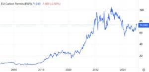
Figure 1 EU Carbon Permit price graph
This means that the price per ton of natural gas is roughly 10 times higher than that of CO₂. As a result, a CO₂ transport system operator must transport about 10 times more CO₂ to generate the same revenue as a natural gas pipeline operator. This creates a natural economic incentive to maximize throughput in CO₂ transportation.
We`ll further explore that dense phase pipeline is not easy to operate, but it is a luck that CO2 can be transported in liquid phase! Otherwise, it would have been financially not viable to transport CO2 via pipelines in CCS.
1.1. Transportation of dense phase is less energy consuming?
The diagram below shows CO₂ pipeline operating range in dense phase, marked in green. As you can see, the density of dense-phase CO₂ is between 800–1000 kg/m³, while gaseous CO₂ at the same temperature has only 200 kg/m³.
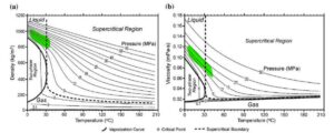
Figure 2 CO2 density and Dynamic viscosity
This means that for the same maximum flow velocity, a pipeline in dense phase can transport up to 5 times more CO₂ than in gas phase.
Some may notice that viscosity of dense-phase CO₂ is 6 times higher (0.12 vs. 0.02 mPa·s), so pumping it needs more energy. But energy loss (head loss) depends on viscosity in power of ¼, so the real increase is only 6^(1/4) ≈ 1.56 times.
λ – turbulence flow friction factor
ν – dynamic viscosity
When switching from gas phase to dense phase, an operator will spend 1.56 times more energy (money) but will be able to transport 5 times more CO₂. In other words, this results in a 5-fold revenue increase at the cost of only a 1.56-fold energy increase. Energy cost is a substantial part of OPEX, and since the industry aims to reduce CO₂ emissions, dense-phase transport is both financially and environmentally beneficial.
However, the reflection above is not a full cost-value analysis, as it does not account for liquefaction costs, the entire supply chain, or the higher CAPEX of a hypothetical CCS pipeline.
That said, it boldly demonstrates that liquid-phase CO₂ transport:
• Reduces transport energy costs and associated carbon emissions
• Significantly enhances the financial feasibility of CCS projects
• Enables industrial-scale CO₂ transport
2. What is the phase diagram of CO2 and why is it important?
There are two types of phase diagrams, look at the figures below: the graphs represent Pressure and Temperature, both describe pure CO2. However, there is an obvious difference between two diagrams. This is because of the vertical axis scale:
• The diagram on Figure 3 uses a logarithmic scale. It enables to describe behavior in a full range, up to 1000 MPa, this is far beyond pipeline transport range.
• The diagram on Figure 4 uses a linear scale, which is limited but easier to read and understand.

Figure 3 CO2 phase diagram – logartihmic axis
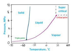
Figure 4 CO2 phase diagram – linear axis
Now, imagine you have two pure substances: N2 (nitrogen) and CO2 (carbon dioxide). Imagine you keep them in identical containers at the same pressure and temperature (-30˚C and 2 MPa)
• N2 will be in gas phase – see Figure 5, the point is beyond the graph axis
• CO2 in liquid phase – see Figure 4
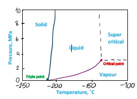
Figure 5 Nitrogen phase diagram
Now, let`s mix these two gases keeping the same pressure and temperature. What do you expect to see? Gas or liquid? You see both. So now there is a part of the diagram where both phases exist. The mixture phase behavior is then described by a diagram which has a shape of a tongue. See Figure 6
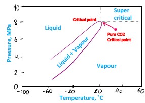
Figure 6 Carbon dioxide with impurities phase diagram
• Inside the tongue both gas and liquid phases exist
• Above the tongue – only liquid (higher pressure, lower temperature)
• Below the tongue – only gas.
The shape and location of the diagram depends upon composition of the mixture, including impurities that described below. As it is shown on the graph above, impurities change the critical point of the mixture, for example, N2 increases the pressure and reduces the temperature of critical point. Often impurities increase both pressure and temperature of critical point, making it harder to reach and maintain dense phase.
A phase diagram illustrates the conditions (pressure and temperature) under which a substance exists in different phases—solid, liquid, and gas. Knowing these parameters is paramount for design and operations of pipelines. A designer and an operator goal is to stay in dense phase.
Note: some sources use different terminology for this state. We will use dense phase to describe both liquid (above critical pressure) and supercritical CO2.
3. Why is it important to know impurities?
Every project we have been involved in has shown a strong focus on CO₂ specification. While several industry codes define the general specifications for CO₂, no operator is fully satisfied with these standards.
Impurities have following impacts:
1. Shift in CO2 phase behavior
For example, the presence of N₂ increases the critical pressure of CO₂. This means that the pipeline must operate at a higher pressure to maintain single flow (above the saturation line on phase diagram). For instance, the critical pressure of pure CO₂ is approximately 70 barg, but impurities can raise this value to 80 barg.
To maintain a safe margin between operating pressure and phase change pressure (to prevent bubble formation in the flow), a 50 barg increase in design pressure should be assumed. Since pipeline wall thickness is a linear function of pressure, this implies that a CO₂ pipeline would require approximately 50% more steel compared to a typical gas pipeline (150 barg / 100 barg, where 100 barg is a standard gas pipeline design pressure, and 150 barg is the CO₂ pipeline design pressure). This approximation does not account corrosion allowance, fabrication tolerances and standard wall thicknesses. Increase of the wall thickness leads to significant increase of the project cost:
a. Procurement of line pipes is substantial in total cost of the project
b. Onshore and offshore logistics of line pipes
c. Heavier line pipes require larger vessel with larger tensioner and/or limited weather workability
d. Thicker wall thickness reduces pipelay rate
2. Increased corrosivity
For example, NOₓ and SOₓ are highly corrosive substances when they participate in reactions that form strong acids. Publicly available CO₂ specifications limit the maximum concentration of these impurities to 5 ppm on average. However, achieving this level of purity is both difficult and expensive for CO₂ capture plants, and conventional sensors struggle to measure such low impurity concentrations accurately.
3. Shift in impurities solubility compared to pure CO2
Knowing water solubility in CO2 is important to ensure no free water in the pipeline. If free water is present in the flow, then strong carbonic acid will form, leading to extensive corrosion.
Impurities like H2 or N2 reduces water solubility in CO2, hence increasing the chance of free water drops. See Figure 7. It should be noted that in a depressurization scenario, when the vapour phase forms, vapour bubbles can contain much less water than the dense phase, hence free water can form in the gas phase.
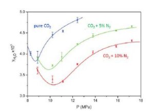
Figure 7 Water solubility in CO2 with impurities (Foltran et al, 2015)
Another example of a hazard due to different solubility of liquid and gas phase: Recommended max concentration of H2 (hydrogen) is 1 % mol. It is deemed safe as long as the flow is in dense phase. However, in a depressurization scenario bubbles form. H2 molecules move to gas phase, because H2 is a light molecule that finds an equilibrium in lower density gas phase. The concentration of H2 in gas phase can grow tenfold. Increased concentration of H2 combined with high pressure and high temperature, poses hydrogen embrittlement risk for pipeline steel.
![]()
Figure 8 Illustration of vapour phase containing H2
These examples amplify the influence of impurities to the phase diagram, solubility and corrosivity that has to be accounted in operation.
3.1. Why does CO2 contain impurities different than natural gas?
Unlike natural gas, CO₂ streams contain various impurities. This is primarily because most CCS (Carbon Capture and Storage) projects aim to capture CO₂ from emitters burning natural gas or coal. During combustion, multiple chemical reactions occur in the presence of nitrogen (N₂) from air, hydrogen sulphide (H₂S) from natural gas, and high temperatures. As a result, CO₂ captured from exhaust gases contains impurities such as NOₓ, SOₓ (where “x” represents a variable number of oxygen molecules), N₂, CH₄, H₂O, and others.
Varieties of impurities in CO2 and their effect (as discussed above) must be thoroughly examined at design stage and considered at operations stage.
4. Are both NG and CO2 pipelines operated differently?
As discussed above, CO₂ flow may contain a wider variety of impurities; therefore, a CO₂ pipeline operator needs to monitor more parameters than a natural gas pipeline operator. In most cases, an NG pipeline operator monitors the following:
1. Pressure and temperature
2. Hydrocarbon composition (methane, ethane…)
3. Water dew point – to ensure no free water forms in the pipeline under the most unfavourable conditions
4. Hydrocarbon dew point – to prevent the formation of liquid hydrocarbons and potential slugging in the pipeline
5. H₂S concentration – for corrosion prevention
6. CO₂ concentration – as carbon dioxide can react with free water to form carbonic acid, leading to corrosion
For example, corrosion engineers of NG operator when using corrosion rate prediction software like Hydrocor, would in most cases only consider CO₂ and H₂S as impurities input parameters.
In contrast, a CO₂ pipeline operator must monitor over 30 additional impurities on top of those required for NG. Otherwise, CO₂ pipeline operations are generally similar to NG pipeline operations until transient events occur, such as:
• Controlled depressurization
• Leaks
• Off-spec CO₂
• Shutdowns and startups
The main challenge is typically associated with phase changes and subsequent variations in parameters between the gas and vapor phases. For example, during a shutdown, pressure and temperature along the pipeline equalize. If the pipeline was operated in dense phase, pressure drop along the line during operation is minimal, meaning that even during a shutdown, pressure change due to equalization remains negligible. However, the temperature drop can be significant. The heat capacity of dense-phase CO₂ is approximately three times higher than that of NG. therefore, when CO₂ is running, the temperature drop is relatively slow. Thus, when the flow stops, the difference between CO₂ and ambient temperature is higher. This temperature drop leads to a pressure reduction, which may cause a phase transition to vapor. In the gas phase, water solubility decreases by a factor of 2–4, increasing the risk of free water formation inside the pipeline, see Figure 9
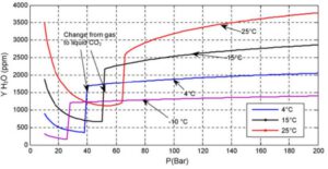
Figure 9 Water solubility in Pure CO2 (Visser et al, 2008)
The consequences of off-spec CO₂ are more critical for pipeline integrity than in NG because corrosion rates can become extreme. This requires a different approach from the operator when off-spec conditions occur, including early alarms and automatic shutdown of safety valves if impurity levels show an increasing trend (even before exceeding a limit). Unlike in NG pipelines, where off-spec gas may be temporarily tolerated, CO₂ pipeline operators must prevent the introduction of off-spec CO₂ at all costs, as corrosion rate is extremely high and it is very difficult to remove.
4.1. Why does CO2 cool faster than natural gas?
Another consequence of molecular properties of the CO₂ is that it has stronger intermolecular forces compared to CH₄. As a result, when pressure decreases, CO₂ consumes more energy during expansion than CH₄, leading to a stronger cooling effect. This means that for the same pressure drop, the temperature reduction in CO₂ is more significant than in CH₄.
Ratio of temperature change to a pressure reduction is called Joule Thomson (JT) coefficient. See the figure below where JT coefficient of different gases at ambient pressure are presented, CH4 curve is placed between N2 and H2.
One shall be aware that coefficient varies for changing pressure and temperature, hence total temperature drop is an integral function of initial and final pressure.
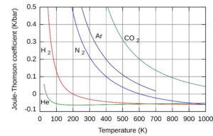
Figure 10 JT coefficient for different gases
If CO₂ is depressurized by 100 bar, it can experience a temperature drop of 50 to 100°C, whereas methane would cool roughly half as much under the same conditions. A 100°C temperature drop is significant from a phase diagram perspective, as it can lead to solid phase formation, given the drastic cooling effect.
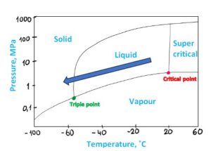
Figure 11 CO2 Phase diagram, JT effect
This property makes it essential to carefully control depressurization during pipeline venting and be aware of the strong cooling effect on the pipeline. While natural gas also requires attention, CO₂ needs even more caution due to its greater temperature drop and risk of solid formation.
Solid CO2 and frozen water formation are seen around the rupture of CO2 pipeline.
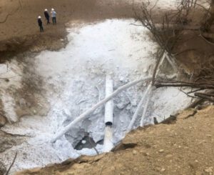
Figure 12 Pipeline rupture and solid CO2 formation
4.2. Why does CO2 deteriorate seals faster than natural gas?
Natural gas operators are aware of unwanted event Rapid Gas Decompression which may lead to seals damage: at high pressure molecules of methane diffuse into the molecular sieve of elastomeric seals. During decompression, if the rate is too high, molecules of CH4 rapidly migrate to a low-pressure region and rupture the seal.
CO2 poses more risk related to molecules interaction. Natural gas is primarily composed of methane (CH₄). The molecular structures of methane and carbon dioxide (CO₂) are shown in the figures below.
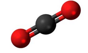

Figure 13 CO2 molecule Figure 14 CH4 molecule
Molecular weight of CH₄ is 16, while CO₂ is 44, so CO₂ molecule is heavier. But CO₂ molecule is linear. Because of this, even though it is heavier, it can pass through molecular sieve of materials easier than CH₄. When CO₂ dissolves into the polymer matrix under high pressure (such as in CO₂ pipelines operating at 150+ bar), it causes the material to swell. This swelling alters the mechanical properties of the polymer, making it softer and reducing its strength. If the swelling is excessive, it can lead to deformation, loss of sealing capability, and mechanical failure.
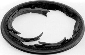
Figure 15 Example of deteriorated polymer
Therefore, either metal to metal sealing or designated materials shall be selected for CO2 transport.
4.3. Why are CO2 pipelines more prone to Running Ductile Fracture than NG pipelines?
Let`s break down the term Running Ductile Fracture (RDF)
- It is a fracture of the pipeline wall, caused by a combination of a pipe defect and internal pressure.
- It is ductile, not brittle, meaning the material deforms before breaking, requiring more energy to propagate.
- The fracture runs along the pipeline axis, potentially extending over long distances.
The figure below illustrates the difference between brittle and ductile fractures in terms of energy required to break the material: the total area under the strain-stress curve. Higher energy absorption is preferable, as it ensures that the pipeline material has sufficient toughness to fail in a ductile manner rather than a brittle one.
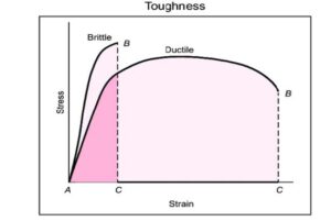
Figure 16 Stress/Strain curve for brittle and ductile materials
A fracture in the pipeline wall leads to a leak, which in turn causes rapid depressurization. Due to the Joule-Thomson (JT) effect, this pressure drop results in a temperature decrease. Since the JT effect is more severe for CO₂ than for natural gas, the cooling effect is more extreme. If the temperature drops too much, the pipeline steel may become brittle, increasing the risk of fracture propagation. Therefore, the first design goal is to ensure that the steel remains ductile at the lowest anticipated temperature, avoiding embrittlement.
However, even if this requirement is met, a fracture can still propagate along the pipeline.
One reason is the heat-affected zone (HAZ) of the longitudinal weld in the line pipe. During the welding process, this zone experiences localized hardening, which reduces its toughness, making it more prone to fracture propagation. To mitigate this risk, longitudinal welds are intentionally misaligned when constructing the pipeline to prevent fractures running along longitudinal welds.
To understand the second and main reason for Running Ductile Fracture (RDF), imagine two simultaneous processes occurring with the wall:
- Internal pressure generates hoop stress in the pipe wall. At the tip of the fracture, the hoop stress pulls the material apart, causing the fracture to propagate perpendicular to the hoop stress, which means it runs parallel to the pipeline axis. The speed of fracture propagation in modern pipeline steels ranges from 100 to 200 m/s, and this speed is non-linearly dependent on pressure.
- At the same time, the leak causes a pressure drop. However, this pressure reduction does not occur evenly along the entire pipeline. Instead, a decompression wave propagates along the pipeline, reducing the pressure progressively.
This creates a competition between two “runners”: the Crack and the Decompression Wave. The outcome depends on their relative speeds:
- If the crack propagates faster or equal to the decompression wave, the fracture will continue running until it encounters a section with a thicker wall or another obstacle. This is called Running Ductile Fracture (RDF) and can lead to long sections of pipeline failure.
- If the decompression wave moves faster than the crack, then at a certain distance, the pressure at the fracture tip will drop enough that the hoop stress is no longer sufficient to drive the fracture forward. This critical pressure is called “arrest pressure”, and it stops the fracture from propagating further.
This last scenario is illustrated in the figure below, emphasizing the importance of controlling pipeline design parameters to ensure that the decompression wave outruns the crack, effectively preventing a catastrophic, long-running fracture.
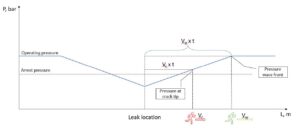
Figure 17 Illustration of fracture propagation vs pressure wave Having studied the picture above, it is easier to comprehend so called “two curve model” on the Figure 18:
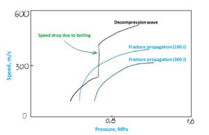
Figure 18 Two curve model diagram
• Decompression wave speed is higher than fracture propagation speed at high pressure
• When dense CO2 boils, decompression speed rapidly decreases
• Due to the decompression speed drop, the fracture becomes faster than decompression wave, hence risk of RDF increases (see the 100 J curve)
Solving the model exactly is quite complex due to constantly changing parameters of the equation: Pressure, Decompression speed and Wave propagation speed. Therefore, conservative and reasonable approach is adopted: RDF does not happen as long Decompression Wave speed is always above Crack Propagation speed.
A steel with higher toughness (300 J in the example above) can be selected to prevent RDF, because the higher toughness stell has lower fracture propagation speed and therefore ensures that RDF does not occur.
Since natural gas is transported in gas phase, such a drop in decompression wave speed does not exist, making toughness requirements less demanding. This is especially critical when repurposing existing natural gas pipelines for dense-phase CO₂ transport, as standard NG pipeline materials may not have sufficient fracture toughness to prevent RDF in CO₂ service.
Conclusion
While there are many similarities between natural gas and carbon dioxide pipeline transport, key differences arise due to the distinct phase behavior and molecular structure of CO2. Anyone involved in the design, repurposing, or operation of CO2 pipelines must understand these differences and take steps to mitigate the challenges they present.
That said, CO2 pipelines can be designed and constructed similarly to natural gas pipelines. The industry and technologies for CCS pipeline transport are well established and have been successfully implemented in various projects worldwide, providing a strong foundation for future developments.